
Industrial MGD Filtration Systems
Engineered for continuous, high volume water treatment. Our redundant A-B line architecture delivers uninterrupted filtration at 832 GPM per array, scalable to any industrial or municipal requirement.
Redundant A-B Line Architecture
Each system uses a redundant A-B line architecture with pressurized stainless-steel canisters, each holding 104 proprietary filters (or adjusted depending on volume). This design provides continuous operation, safe filter change-outs, and scalable flow capacity for large industrial or municipal applications.
Intake
Water enters from industrial discharge
Filtration
Gravity assisted flow through 104 filters
Switch
Auto line swap at 32 to 35 PSI
Output
Clean water to destination
1. System Layout and Vessel Configuration
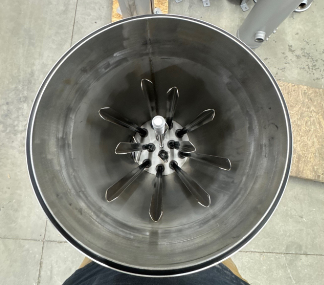
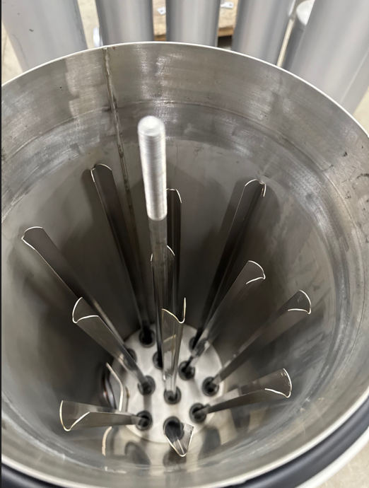
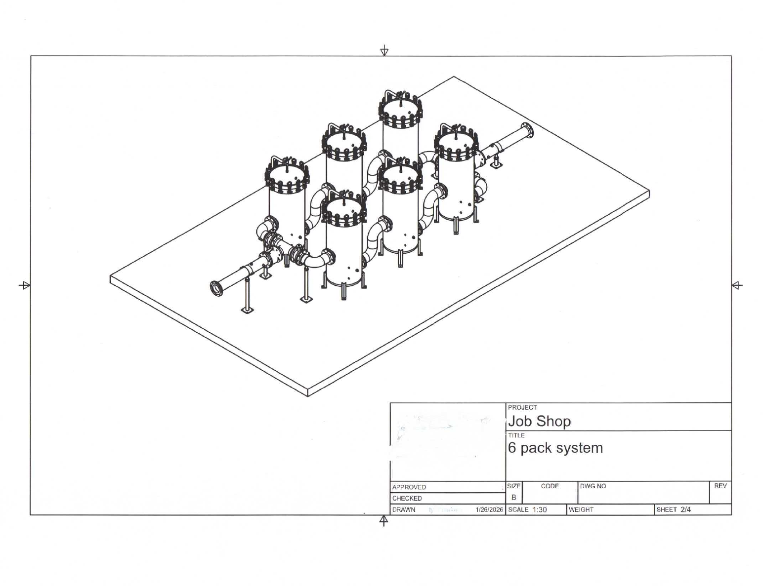
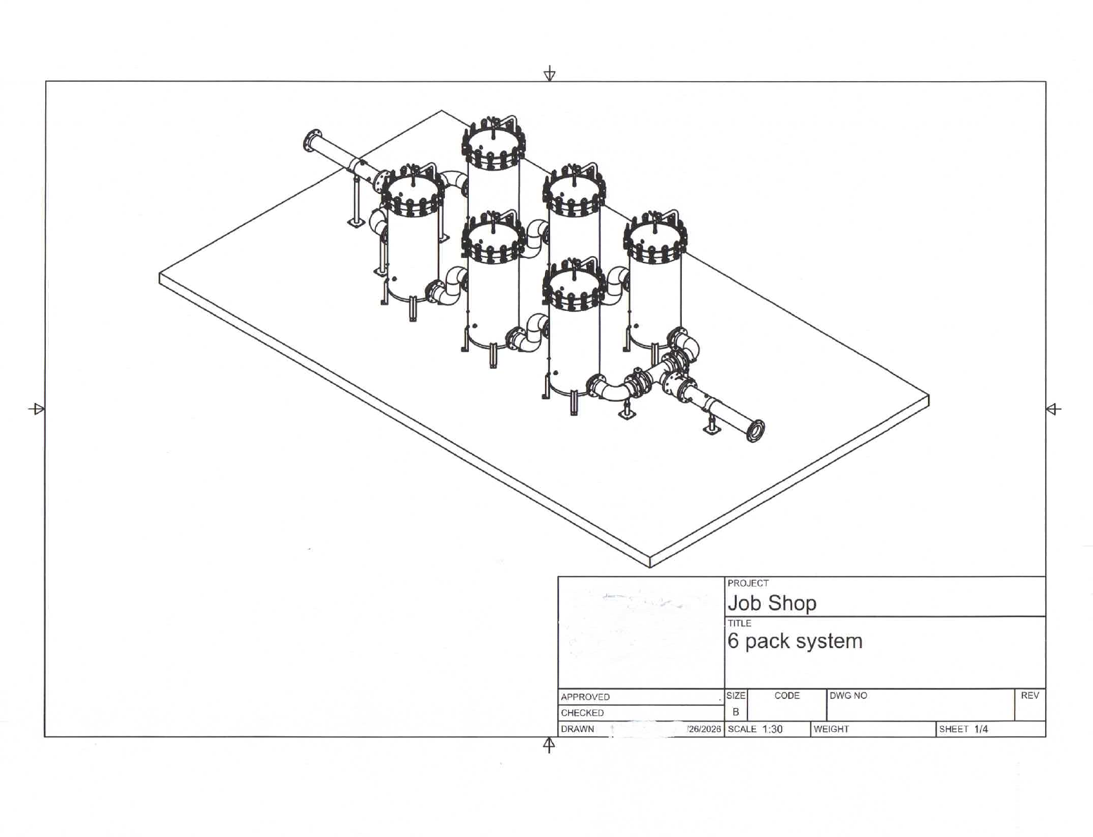
- Each filtration line, Line A and Line B, contains at least a 3-canister inline array. See images below.
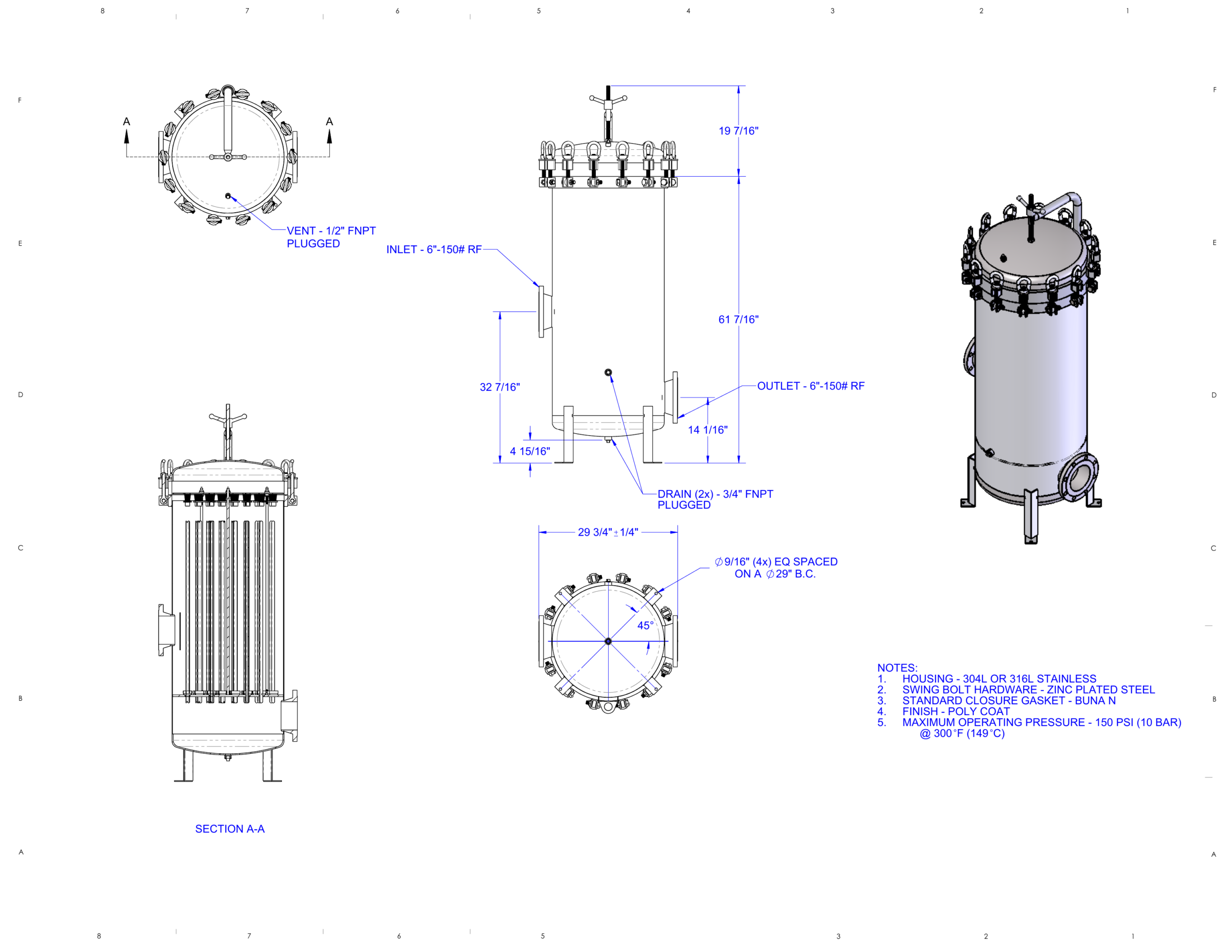
- Each canister holds 104 proprietary filters, maximizing surface area and contaminant loading.
- The two lines operate in a redundant, alternating cycle controlled by diverter valves.
- All canisters are stainless-steel, pressurized vessels designed for industrial duty cycles. See images below.
2. Flow Capacity and System Sizing
A single 3-canister inline array (one line) processes approximately:
Because the system is modular, total plant capacity is determined by the number of A-B sets installed.
Flow Based Sizing Logic
- Required industrial flow rate determines number of A-B arrays
- Each A-B pair provides 832 GPM continuous operation
- Additional arrays are added in parallel to meet higher flow demands
This allows the system to scale from small industrial sites to large municipal or multi-industry campuses.
3. Normal Operation (Line A Active)
During Standard Operation
- Diverter valves direct all incoming water into Line A.
- Water enters the system from above the canisters, pumped from the industrial discharge point.
- Once inside the vessels, the system transitions to gravity-assisted flow, reducing energy demand and mechanical wear.
- As filters load with contaminants, pressure gradually increases.
Pressure Threshold
When differential pressure reaches 32 to 35 psi, the system automatically switches lines.
4. Automatic Line Switching
At the pressure threshold:
- The diverter valve closes Line A
- Flow is instantly redirected to Line B
- Line B becomes the active filtration line
- Line A is now depressurized and safe for maintenance
This ensures 100% uptime with no interruption to industrial operations.
5. Safe Filter Replacement (Line A Offline)
With Line A Depressurized:
- Operators remove the pressurized cap from each canister
- Spent filters are removed and replaced
- New filters are installed
- The canister is locked down and pressure tested
- Line A is now ready for the next cycle
When Line B reaches 32 to 35 psi, the process reverses.
6. Post-Filtration Water Handling
After Water Exits the Filtration System
- It may flow by gravity to the next stage, or
- A transfer pump may be required depending on the elevation and distance to the clean water destination
This flexibility allows the system to integrate into:
- Industrial reuse loops
- Discharge to holding ponds
- Municipal treatment systems
- Direct environmental release (where permitted)
7. Key Advantages
3-Cannister Inlay Array and Cannister and Rods View
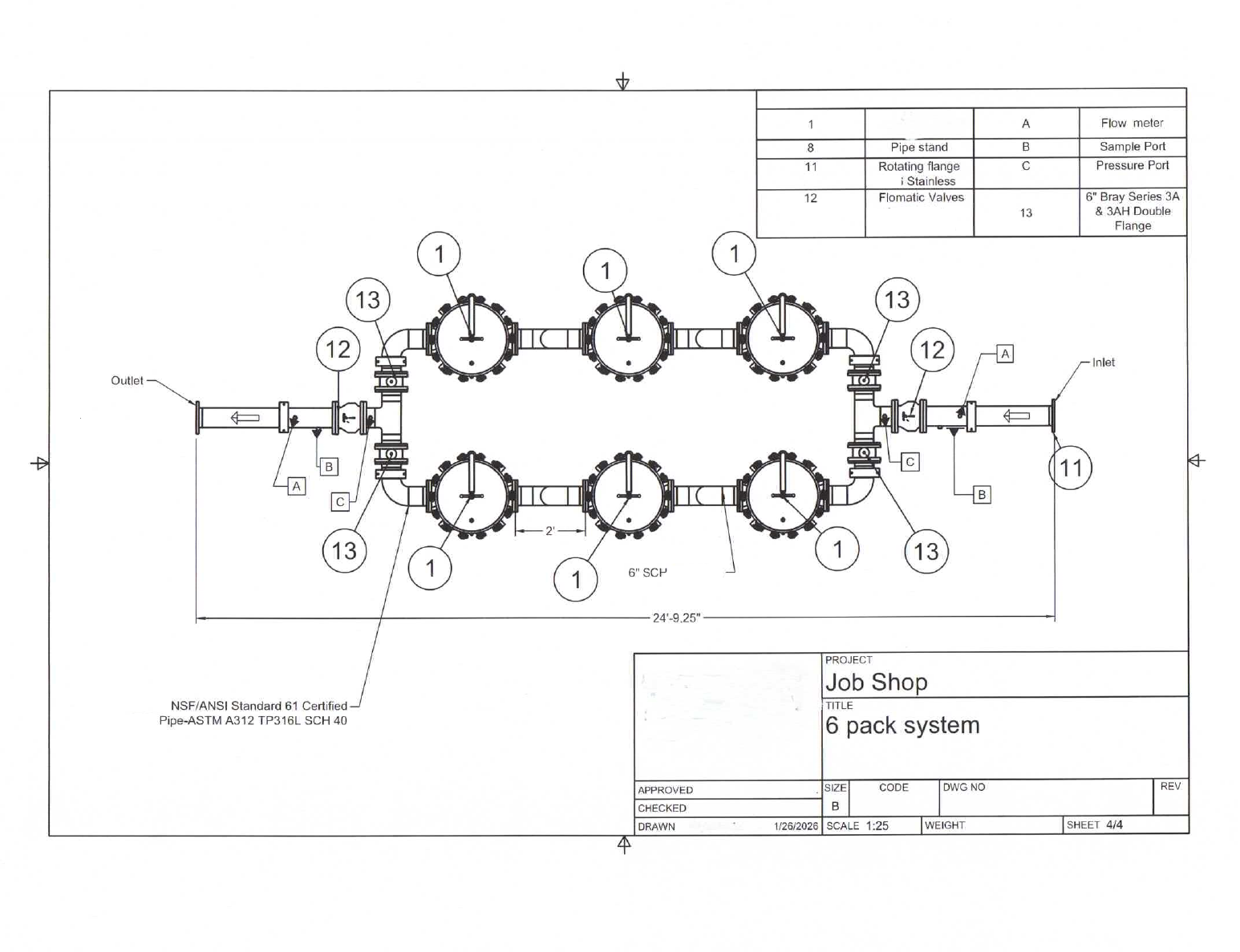
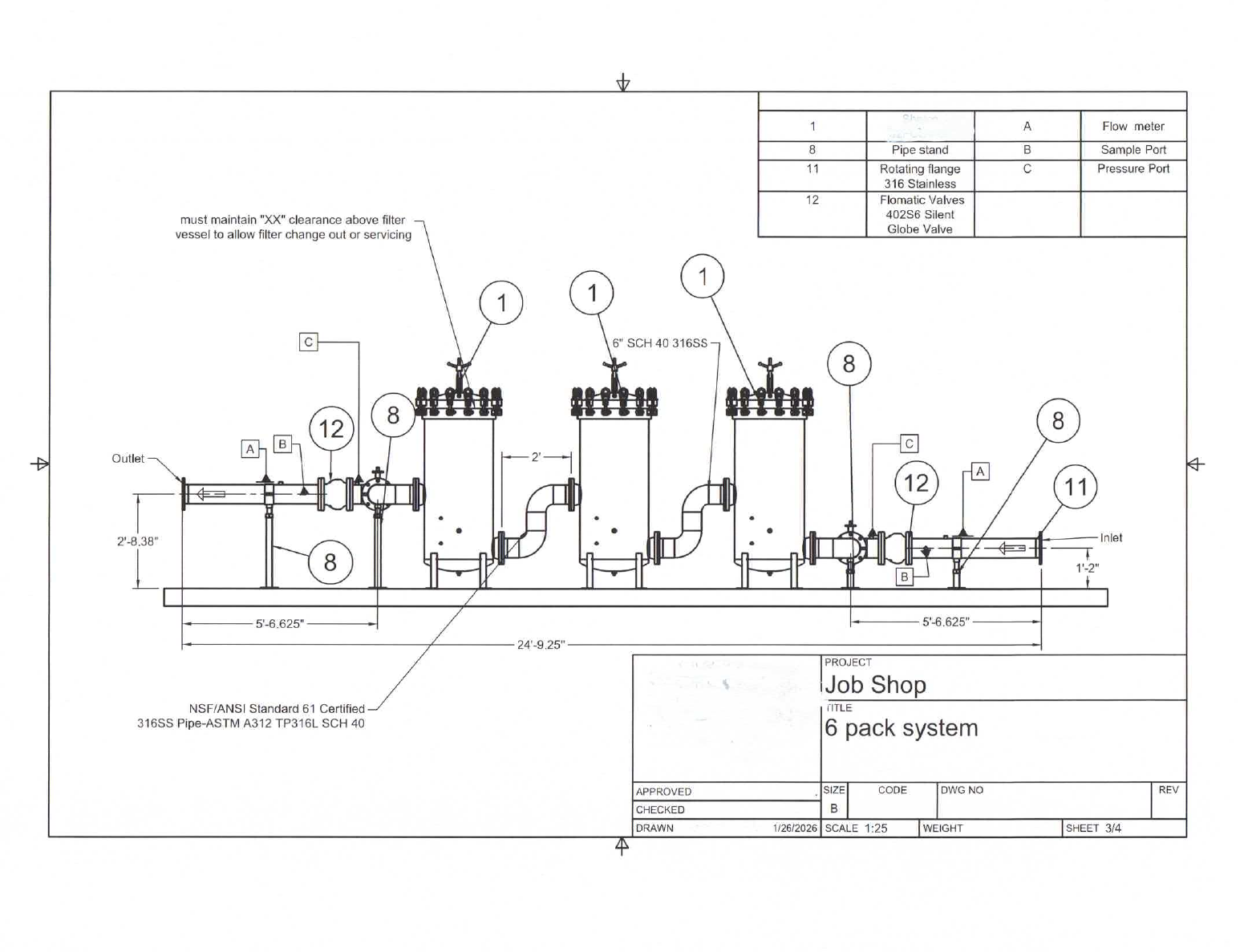
Industrial MGD Systems Diagram
The full uploaded diagram is embedded below as rendered pages so the page keeps the exact visual reference while still being easy to edit in HTML.
Industrial water treatment engineered for uptime.
Ready to discuss your industrial or municipal water treatment needs? Tell our team about your project and request a custom quote.
Request a Custom Quote